Peer to peer AC control with an inverter and a synchronous rectifier
Overview
Peer-to-peer communication in power electronics involves two converters, a DC/AC converter producing a certain power and informing an AC/DC converter that it can consume this reference power.

DC/AC Converter (single phase inverter): This converter is responsible for converting direct current (DC) power into alternating current (AC) power. It may be connected to renewable energy sources (such as solar panels or wind turbines) or batteries, which produce DC power. The DC/AC converter's task is to generate AC power for use in the electrical network.
AC/DC Converter (single phase synchronous rectifier): This converter performs the opposite function. It converts AC power back into DC power. This conversion is necessary when the electrical network requires DC power for various applications, such as charging batteries or powering DC devices.
In a peer-to-peer communication system, these converters communicate with each other to optimize power exchange. The DC/AC converter informs the AC/DC converter of the available power it can deliver. This information includes details like the power's magnitude and frequency.
An important aspect of this exchange is that the DC/AC converter must maintain an alternating current in phase opposition (180 degrees phase shift) with the input alternating voltage. This phase opposition ensures that power is effectively delivered to the load.
A proportional resonant is used to keep the input alternative current in phase opposition with the Vac, a PI is used to control the output voltage Vdc.
Requirements and schematic
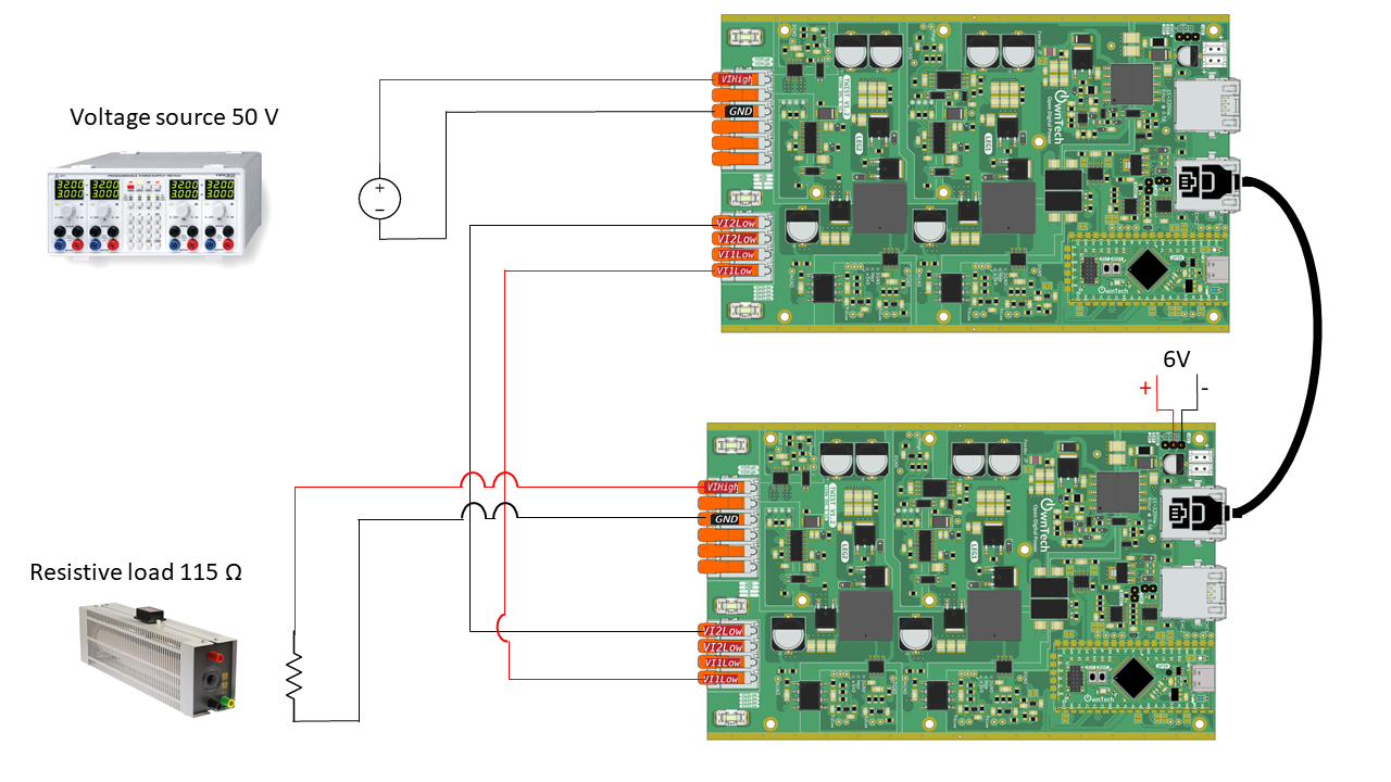
You will need :
- Two Twist
- A 50V DC power supply (input voltage for the inverter)
- A 6V DC power supply (external sensors/drivers suply for the synchronous rectifier)
- A 115Ω resistive load
- A RJ45 cable
It is important to check that the boards you are using have the correct voltage and current measures since they'll be used to compute the duty cycle.
Instruction to flash the code, and view some results
To flash the code
This example depends on two libraries:
- control_library
- ScopeMimicry
To use them, you have to add the following lines in platformio.ini file:
lib_deps=
    control_library = https://github.com/owntech-foundation/control_library.git
    scope = https://github.com/owntech-foundation/scopemimicry.git
In src/main.cpp at the line n. 48 you have a macro that defines wether you are flashing the inverter or the synchronous rectifier.
To flash the inverter, choose :
To flash the synchronous rectifier, choose :
Here P_ref = 19W to have a 47V output DC voltage. You can change this value in line 87 of src/main.cpp file.
After that, connect to the inverter serial monitor and press p to start power flow. Press i to stop.
To view some variables.
After stop i.e. in IDLE mode you can retrieve some data by pressing 'r'. It calls a
function dump_scope_datas() which send to the console variables recorded during
the power flow phase.
But before running, you have to add one line in the file platfomio.ini
And you have put the python script filter_datas_recorded.py in a monitor directory
which must be in you parent project directory. Then the script should capture the
console stream to put it in a txt file named year-month-day_hour_minutes_secondes_record.txt.
These files can be plotted using the plot_data.py python script if you have the
matplotlib and numpy modules installed.
Expected results
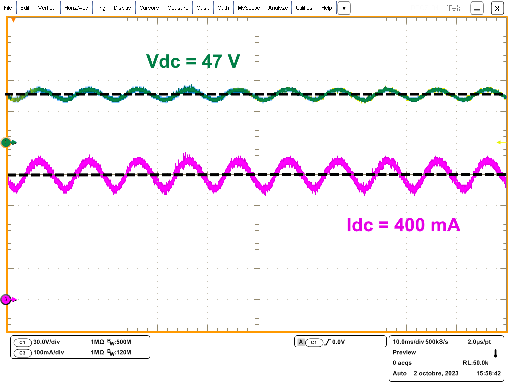
If everything goes well you'll have 47V delivered to the resistor.
Here are some results for Vdc and Idc :
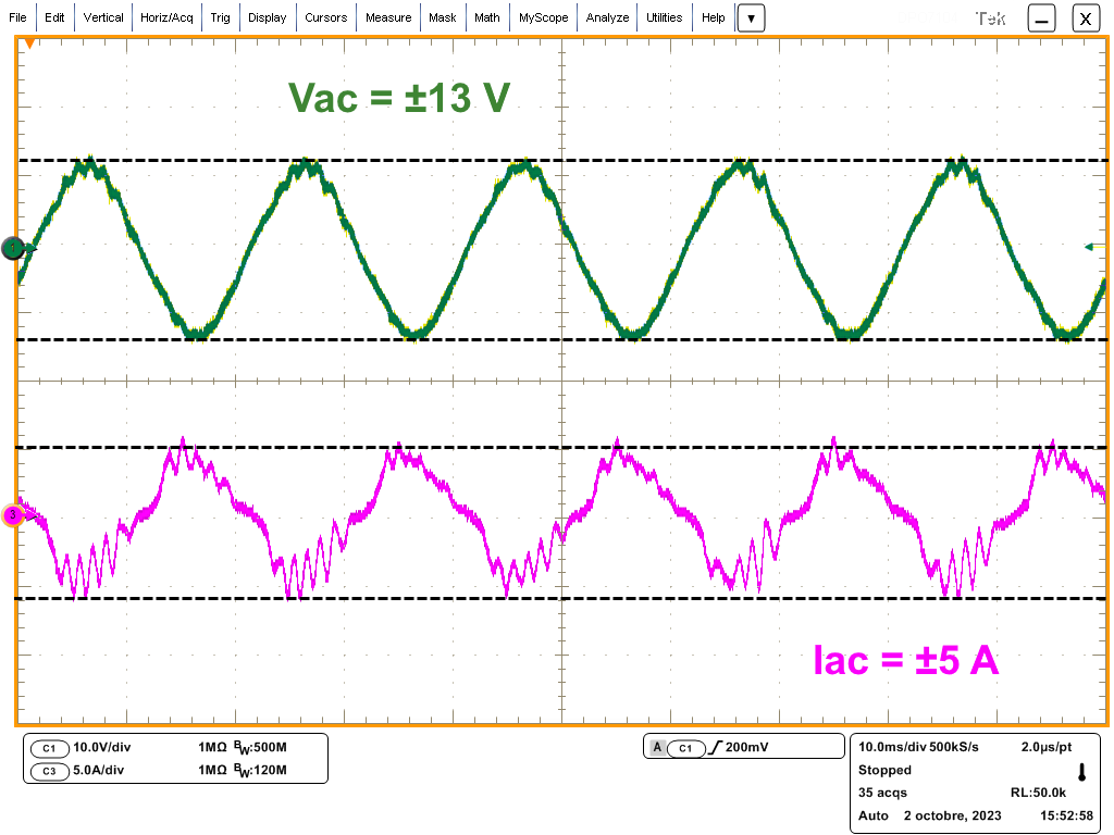
And for Vac and Iac :
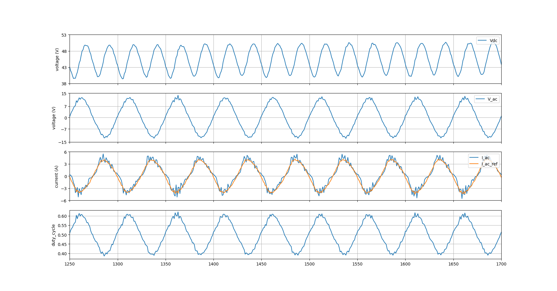
By using the python script you can also watch MCU internal variables :