Ac current source follower
In this example you need to have a first Twist with the Grid Forming example.
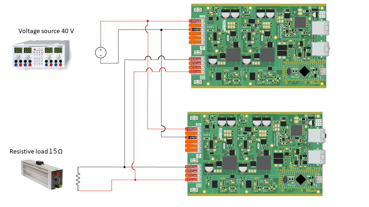
The parameters are:
- \(U_{DC} = 40 V\)
- \(R_{LOAD} = 15 \Omega\).
In the second Twist we use a software phase locked loop ( "PLL" ). By this way we are synchronised with the grid voltage and we can then inject current with a power factor of one. The current is regulated using a proportional resonant ("PR") regulator.
Software overview
Import a library
the "pll" and "pr" are provided by the OwnTech control library which must be included
in the file platfomio.ini.
Define a regulator
The Proportional Resonant regulator is initialized with the lines above:
The parameters are defined with these values:
static Pr prop_res; // controller instanciation.
static float32_t Kp = 0.2F;
static float32_t Kr = 3000.0F;
static float32_t Ts = control_task_period * 1.0e-6F;
static float32_t w0 = 2.0 * PI * 50.0;   // pulsation
Configure the PLL
You have to define a PLL:
Then initialize it:
and use it:
The calculation return a structure with 3 fields:
- the pulsation
win [rad/s] - the angle
anglein [rad] - the angle error
errorin [rad/s]
Link between voltage output and duty cycle
The voltage source is defined by the voltage difference: \(U_{12} = V_{1low} - V_{2low}\).
Link with the duty cycle:
- The leg1 is fixed in buck mode then: \(V_{1low} = \alpha_1 . U_{DC}\)
- The leg2 is fixed in boost mode then: \(V_{2low} = (1-\alpha_2) . U_{DC}\)
We change at the same time \(\alpha_1\) and \(\alpha_2\), then we have : \(\alpha_1 = \alpha_2 = \alpha\).
And then: \(U_{12} = (2.\alpha - 1).U_{DC}\)
\(\alpha = \dfrac{U_{12}}{2.U_{DC}} + 0.5\)
Retrieve recorded datas
After stop i.e. in IDLE mode you can retrieve some data by pressing 'r'. It calls a
function dump_scope_datas() which send to the console variables recorded during
the power flow phase.
But before running, you have to add one line in the file platfomio.ini
And you have to put the python script filter_datas_recorded.py in a monitor directory
which must be in you parent project directory. Then the script should capture the
console stream to put it in a txt file named year-month-day_hour_minutes_secondes_record.txt.
These files can be plotted using the plot_data.py python script if you have the
matplotlib and numpy modules installed.