Working with multiple PWM
The spin has a total of 5 PWM channels with 2 complementary output each. In this example, we'll detail how to use each of them.
Hardware setup and requirements
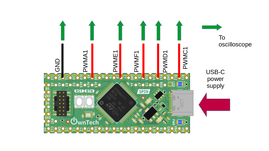 figure 1
You will need :
- A spin
- A usb-c cable to supply the spin
- An oscilloscope to watch PWM waveform
We can watch :
-PWMA1 on gpio A8 -PWMC1 on gpio B12 -PWMD1 on gpio B14 -PWME1 on gpio C8 -PWMF1 on gpio C6
Software setup
This example is initializing every PWM, and making a phase shift 77° (= 360/5°) as if we working in interleaved mode. See the phase shift example for more details.
The duty cycle is the same for both PWMA and PWMC.
You can control the duty cycle from the serial monitor :
- press u to increase the duty cycle
- press d to decrease the duty cycle
See ownplot if you would like a better graphical interface for the serial monitor.
Expected result

You should observe 5 PWM with a phaseshift of 77° between them.