Open loop buck control
This section of the tutorial will show you how you can generate a code to control the converter in open-loop mode with the simulink template.
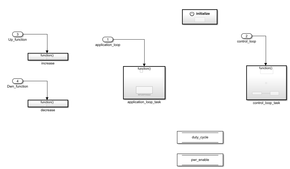
First let’s start by creating a variable which will represents the duty cycle. Take a “data store memory” block from simulink, to the root (where pwr_enable is located).
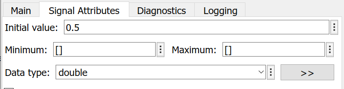
Name this data store block duty_cycle, and in the signal attribute tab choose the initial value (0.5 here to have 50% duty cycle) and data type (double or float):
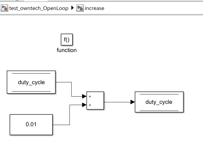
Then enter inside the increase function block, take a “data store read” and a “data store write” from simulink library and link them with duty_cycle (name them duty_cycle). With the association of the “constant” and “add” block from simulink you can form the following schema.
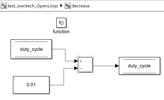
You can do the same thing in the decrease function block, instead of an addition it will be a subtraction.
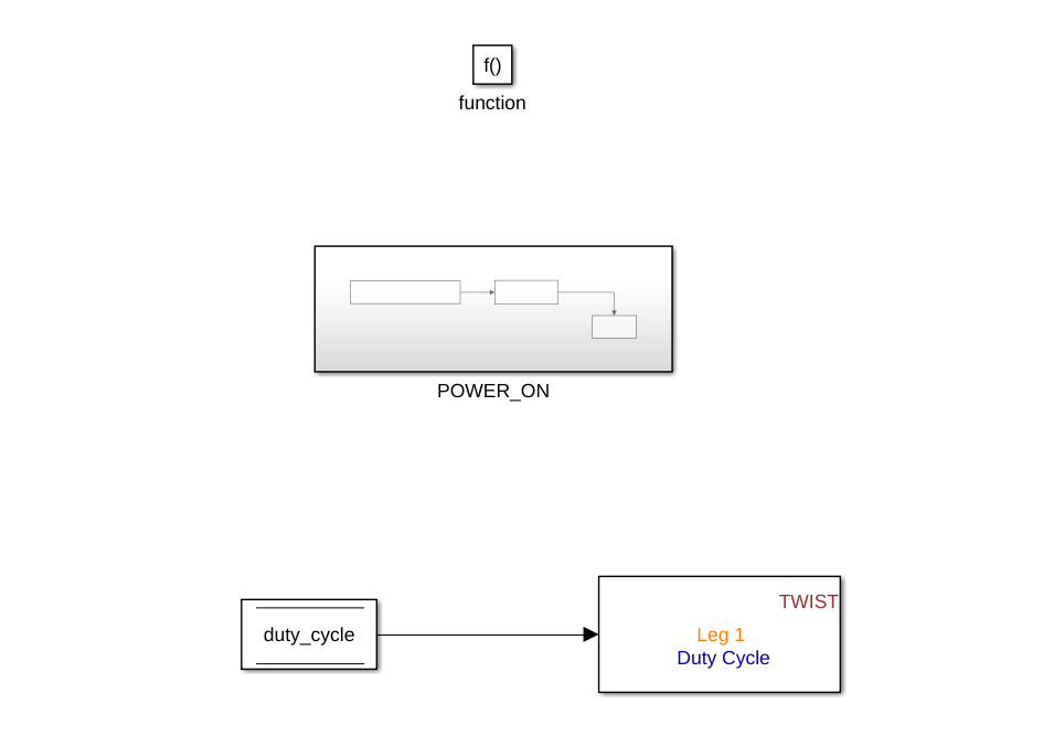
You have now the possibility to control the duty_cycle either by increasing or decreasing it, the only thing missing is sending this value to the converters. Inside control_loop_task, we will first uncomment the POWER_ON to activate power : click on the block then press ctrl+shift+x. We will then place a “data store read” block linked to duty_cycle and a set leg duty block connected together.
Then generate the code, matlab will upload it automatically to the board :

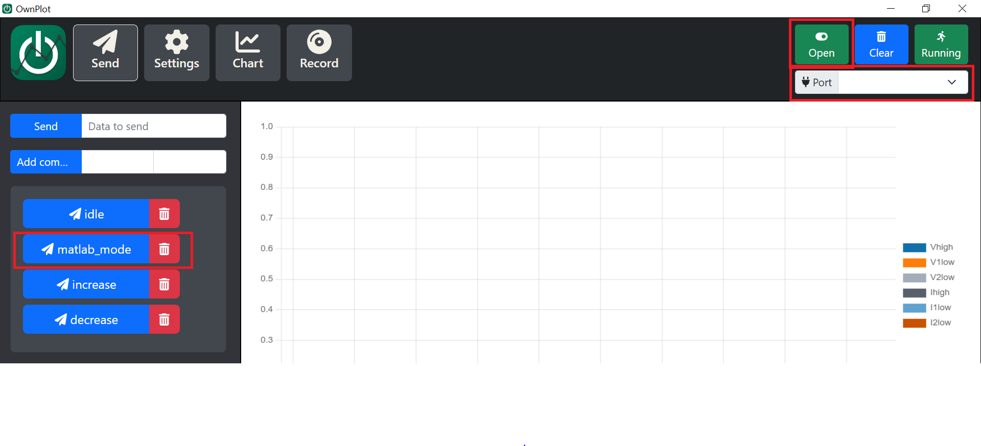
Finally, switch to ownplot, open the correct port and send the matlab_mode to execute the generated code, use increase and decrease function to control the duty cycle :