Triggering measure from ADC via software trigger
An ADC, or Analog-to-Digital Converter, is a crucial component in modern electronics that converts continuous analog signals into discrete digital data. In simpler terms, it takes real-world phenomena, like sound or temperature, and turns them into numbers that a computer can understand and process. This conversion is essential for various applications, in power electronics it allows us to get real-time measures from the circuit like voltage and current.
This example will show you how to get measures from the ADC by calling a function that will trigger the measures : this is what we call a software trigger.
Hardware setup and requirements
You will need :
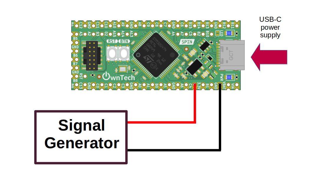
- 1 spin
- A usb-c cable to supply power to the spin, and also upload the code from computer
- A signal generator to create a waveform to measure it from ADC, it can be sinewave, triangle wave...etc. This signal must between 0V and 2.048V
Connect the signal generator to pin C4, and gnd.
Software setup
The ADC 2 is used here, it is initialized like this :
We use the 5th channel of the adc, which is the gpio C4 on the spin (also numbered as pin 35). To enable the acquisition from this pin, we use the functionenableAcquisition:
data.enableAcquisition(2, 35) // Enable acquisition for ADC2, for channel 5 (localized in GPIO C4 / pin number 35)
There is a total of 8 possible pin from where you can get analog measures :
| GPIO | PIN number | ADC and channels |
|---|---|---|
| PC4 | 35 | ADC2 channel 5 |
| PA1 | 30 | ADC1 channel 2 / ADC2 channel 2 |
| PA0 | 29 | ADC1 channel 1 / ADC2 channel 1 |
| PC3 | 27 | ADC1 channel 9 / ADC2 channel 9 |
| PC2 | 26 | ADC1 channel 8 / ADC2 channel 8 |
| PC1 | 25 | ADC1 channel 7 / ADC2 channel 7 |
| PC0 | 24 | ADC1 channel 6 / ADC2 channel 6 |
| PB15 | 6 | ADC4 channel 5 |
You can configure any of the above ADC with same steps.
Expetected results
The analog value measured from the adc is stored inside the variable adc_value, which is printed in the serial monitor every 100ms you can then watch the measured on ownplot.
If everything went correctly, you should observe the same waveform on ownplot that you generate via the signal generator.