Triggering measure from ADC via HRTIM trigger
An ADC, or Analog-to-Digital Converter, is a crucial component in modern electronics that converts continuous analog signals into discrete digital data. In simpler terms, it takes real-world phenomena, like sound or temperature, and turns them into numbers that a computer can understand and process. This conversion is essential for various applications, in power electronics it allows us to get real-time measures from the circuit like voltage and current.
The spin uses the stm32G4 MCU, which has a high resolution timer (HRTIM) which can produce high resolution PWM. This example will show you how to use the HRTIM in order to trigger the measures.
Hardware setup and requirements
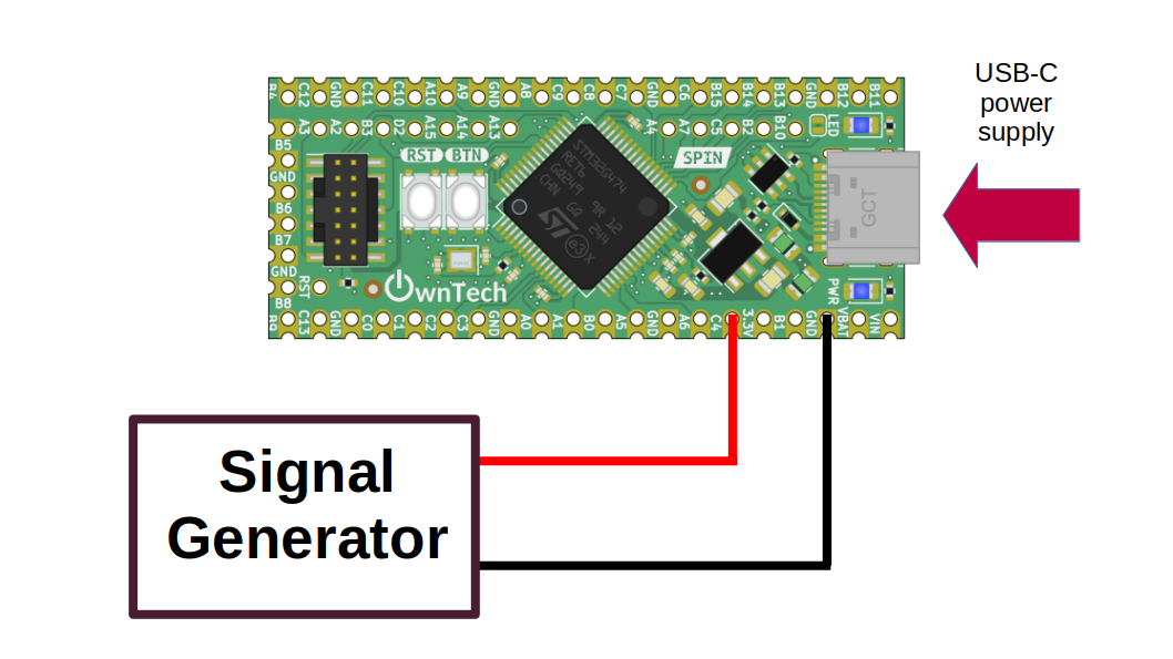 figure 1
You will need :
- 1 spin
- A usb-c cable to supply power to the spin, and also upload the code from computer
- A signal generator to create a waveform to measure it from ADC, it can be sinewave, triangle wave...etc. This signal must between 0V and 2.048V
Connect the signal generator to pin C4, and gnd.
Software setup
The HRTIM has 6 differents timer (A,B,C,D,E,F) but you can choose up to two of them to trigger the measures. In this example we'll show you how you can use one of them the timer A.
On the picture below, you can see the waveform of the timer A pwm, the carrier, the duty cycle and the colored zone represents the timing where the measures is trigerred.
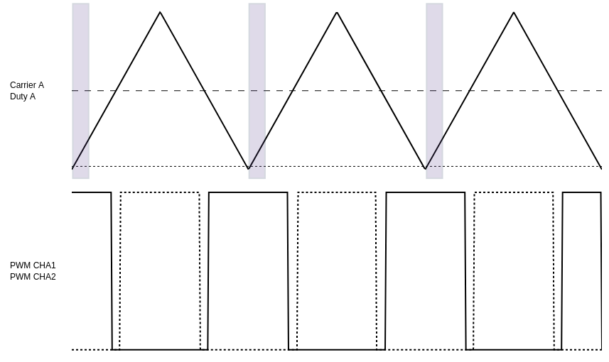 figure 2
The measure is triggered with the same frequency as the switching frequency, the measure is done around the trough of the carrier on the positive slope. We will explain here which functions to call to setup the ADC trigger.
First of all, we start by initializing the PWMA :
    spin.pwm.setFrequency(200000); // Set frequency of pwm

    spin.pwm.setModulation(PWMA, UpDwn); // Modulation mode, here up-down (triangle wave carrier)
    spin.pwm.setAdcEdgeTrigger(PWMA, EdgeTrigger_up); // Trigger on the positive slope

    spin.pwm.initUnit(PWMA); // timer initialization
setAdcEdgeTrigger allows us to choose where we want to trigger the measures : on the positive slope (EdgeTrigger_up) of the carrier like in fig.2, or the negative slope (EdgeTrigger_down) of the carrier.
After the initialization of the PWM, we can link it to a trigger :
    spin.pwm.setAdcTrigger(PWMA, ADCTRIG_1); // PWMA is linked to ADCTRIG_1
    spin.pwm.setAdcTriggerInstant(PWMA, 0.06); // set the trigger instant
    spin.pwm.enableAdcTrigger(PWMA); // enable the trigger
setAdcTriggerInstant will set the moment when we trigger a measure with a parameter between 0 (corresponding to the trough of the carrier)and 1 (corresponding to the crest of the carrier). Here we took 0.06, so we'll get the data around the trough of the carrier (as we have seen on fig.2)
And finally, we set the ADC2 to be set by the ADCTRIG_1, hrtim_ev1 means hrtim external event 1 which is ADCTRIG_1.
We use the 5th channel of the adc, which is the gpio C4 on the spin (also numbered as pin 35). To enable the acquisition from this pin, we use the functionenableAcquisition:
data.enableAcquisition(2, 35) // Enable acquisition for ADC2, for channel 5 (localized in GPIO C4 / pin number 35)
There is a total of 8 possible pin from where you can get analog measures :
| GPIO | PIN number | ADC and channels |
|---|---|---|
| PC4 | 35 | ADC2 channel 5 |
| PA1 | 30 | ADC1 channel 2 / ADC2 channel 2 |
| PA0 | 29 | ADC1 channel 1 / ADC2 channel 1 |
| PC3 | 27 | ADC1 channel 9 / ADC2 channel 9 |
| PC2 | 26 | ADC1 channel 8 / ADC2 channel 8 |
| PC1 | 25 | ADC1 channel 7 / ADC2 channel 7 |
| PC0 | 24 | ADC1 channel 6 / ADC2 channel 6 |
| PB15 | 6 | ADC4 channel 5 |
You can also use ADCTRIG_3 to have PWMC trigger another ADC and get another measure. Below, we reproduce the same step but by using the ADC1 channel 2 localized on PA1 (pin number 30).
start PWMC :
    spin.pwm.setFrequency(200000); // Set frequency of pwm

    spin.pwm.setModulation(PWMC, UpDwn); // Modulation mode, here up-down (triangle wave carrier)
    spin.pwm.setAdcEdgeTrigger(PWMC, EdgeTrigger_up); // Trigger on the positive slope

    spin.pwm.initUnit(PWMC); // timer initialization
    spin.pwm.setAdcTrigger(PWMC, ADCTRIG_3); // PWMA is linked to ADCTRIG_1
    spin.pwm.setAdcTriggerInstant(PWMC, 0.06); // set the trigger instant
    spin.pwm.enableAdcTrigger(PWMC); // enable the trigger
    spin.adc.configureTriggerSource(1, hrtim_ev3); // ADC 2 configured to be triggered by the PWM
    data.enableAcquisition(1, 30); // ADC 2 enabled
Finally you can retrieve data from the ADC :
Expetected results
The analog value measured from the adc is stored inside the variable adc_value, which is printed in the serial monitor every 100ms you can then watch the measured on ownplot.
If everything went correctly, you should observe the same waveform on ownplot that you generate via the signal generator.