Scope simple example
The scope is a powerful tool to inspect electric signals is real time. In this example we will visualize a simple step response of LEG1 PID.
This example will implement a voltage mode buck converter to control the output.
Are you ready to start ?
Before you can run this example, you must have successfully gone through our getting started.
Hardware setup and requirement

Warning
You will need : - 1 TWIST - A dc power supply (20-60V) - A resistor (or a dc electronic load)
Software setup
The software should work out of the box. Build and upload it to the board.
The data to be saved to the scope is structured in the setup_routine.
    scope.connectChannel(I1_low_value, "I1_low");
    scope.connectChannel(V1_low_value, "V1_low");
    scope.connectChannel(I2_low_value, "I2_low");
    scope.connectChannel(V2_low_value, "V2_low");
    scope.connectChannel(duty_cycle, "duty_cycle");
    scope.connectChannel(V_high, "V_high");
    scope.set_trigger(&a_trigger);
    scope.set_delay(0.2F);
    scope.start();
LEG1 and LEG2, the duty_cycle and the V_HIGH are going to be saved. The delay to apply the trigger is of 20% of all the measurements.
Expected result
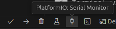
This code will control the output voltage to have 15V, you can control the output voltage with platformio serial monitor. The image below shows your a snippet of the window and the button to press.
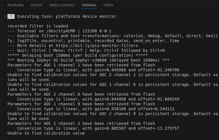
When opening it for the first time, the serial monitor will give you an initialization message regarding the parameteres of the ADCs as shown below.
Tip
- press
uto increase the voltage - press
dto decrease the voltage - press
ato increase the voltage step to be applied - press
zto decrease the voltage step to be applied - press
sto apply the voltage step and automatically retrieve the data - press
rto retrieve the data - press
hto show the help menu
Note
When you send p the Twist board will send you back a stream of data on the following format:
I1 is the current in LEG1 of the LOW side
- V1 is the voltage in LEG1 of the LOW side
- I2 is the current in LEG1 of the LOW side
- V2 is the voltage in LEG2 of the LOW side
- IH is the current in LEG2 of the LOW side
- VH is the voltage on the HIGH side
- VREF is the reference voltage set for LEG1 and LEG2vof the LOW side which is applied during POWER mode.
- VSTEP is the size of the voltage step to be applied for the test.